Cooja: simulating a border router
See tutorial:rpl-border-router instead if you want connect to a network of real (hardware) nodes.
This tutorial will show you how to simulate a RPL border router in Cooja and use it to allow communications between emulated nodes inside Cooja and processes running in the “outside world”.
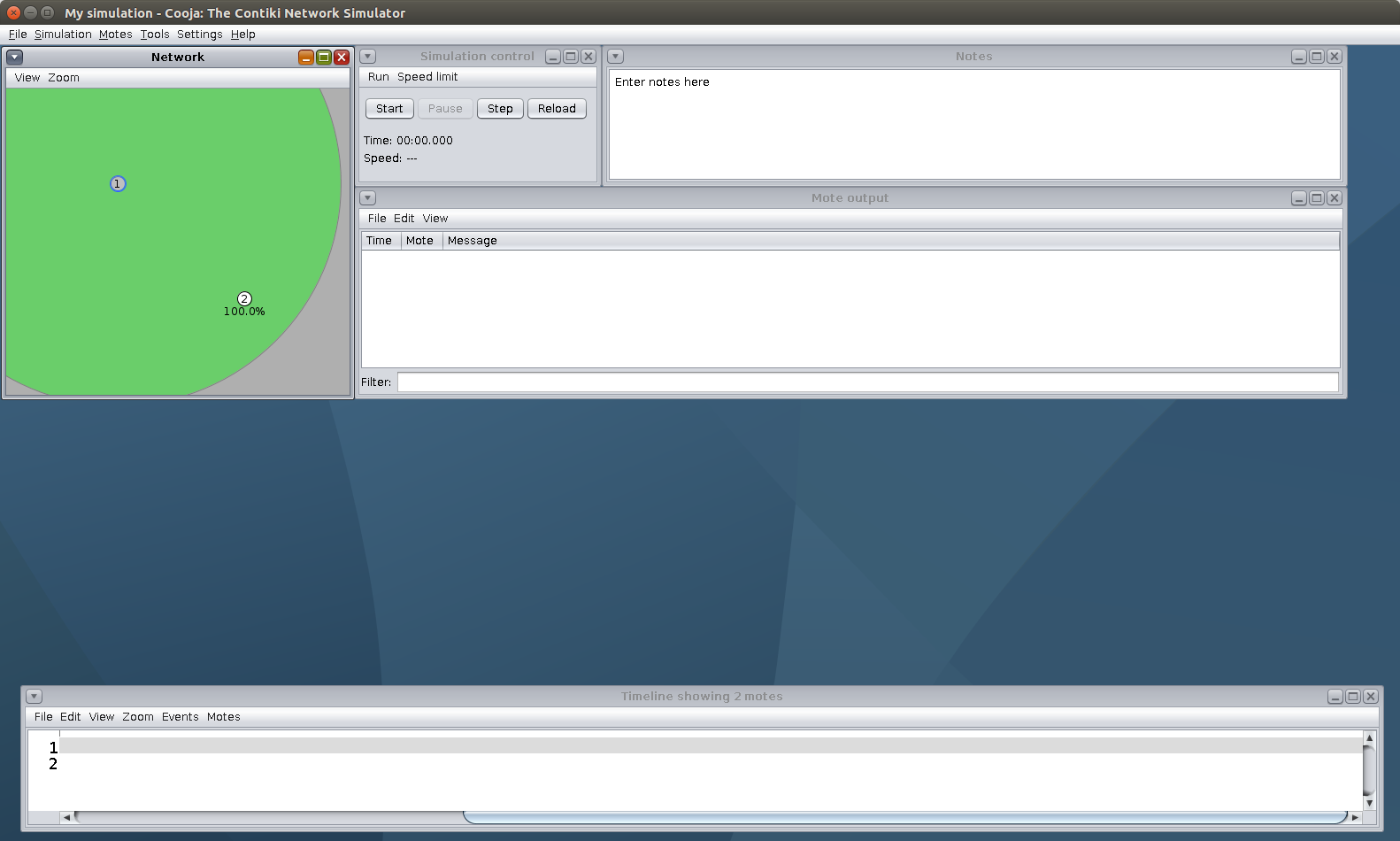
First, create a simulation, as described in tutorial:cooja-getting-started.
Add a new mote type, using the border router example:

Then, add another mote type, e.g., hello-world.
Add one node of each, and place the nodes such as they are within communication range:
To connect the border router to the outside world, we will use a Serial Socket.
This will basically map the border router node’s serial port to a UDP port on the host computer that runs Cooja.
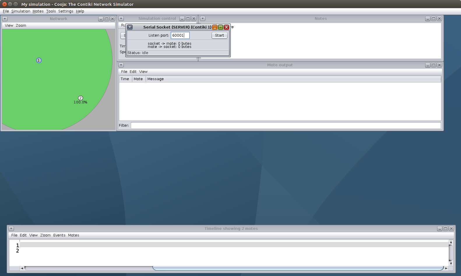
Right click on the border router in the Network view, More tools…, Serial socket (SERVER).
This will create a new window in the Cooja GUI.
By default the UDP port is 60001.
Now click Start in the Serial Socket plugin, and then also in the simulation control to start the simulation.
From a terminal in the same host that runs Cooja, go to examples/rpl-border-router, and run:
$ make TARGET=zoul connect-router-cooja
This will start tunslip6 and will create a virtual tunnel interface (commonly tun0) in the “outside world” environment: your operating system, virtual machine or docker container. tunslip6 will then start acting as a bridge between this tunnel interface and the serial socket inside Cooja:
All traffic originating from inside Cooja will go to through the “serial socket” on to the tunnel interface.
All traffic with a destination address within your simulated network will go through the tunnel interface on to the Cooja serial socket.
In the diagram below, 1 and 2 are two emulated nodes inside Cooja and BR is the emulated border router. Logically, your setup now looks like this:
1<--
   |
   ---> BR <---> Serial Socket <---> tunslip6 <---> tun0 <---> Any process
   |
2<--

|----------Cooja Domain----------|-------------Outside World-------------|
After the simulated RPL network converges, you will be able to reach any node in the network, for example with a ping:
$ ping6 fd00::202:2:2:2
PING fd00::202:2:2:2(fd00::202:2:2:2) 56 data bytes
64 bytes from fd00::202:2:2:2: icmp_seq=1 ttl=63 time=131 ms
64 bytes from fd00::202:2:2:2: icmp_seq=2 ttl=63 time=210 ms
64 bytes from fd00::202:2:2:2: icmp_seq=3 ttl=63 time=199 ms
64 bytes from fd00::202:2:2:2: icmp_seq=4 ttl=63 time=104 ms
64 bytes from fd00::202:2:2:2: icmp_seq=5 ttl=63 time=137 ms
Now keep in mind that, as discussed above, all traffic between Cooja and the outside world goes through this tun0 interface! This means that the source IPv6 address of the ping6 you just ran was the IPv6 address of the tunnel, and it was used as destination address for the ping replies. This address is assigned to the tunnel by tunslip6 and under default settings will be fd00::1.
Any networked process on your host environment will also be able to listen for and receive traffic with that destination IPv6 address. For example, if you want an emulated MQTT client inside Cooja to publish messages to a broker running on the outside, you should configure your MQTT client to send publish messages to the IPv6 address of the tunnel interface (fd00::1).
To check the IPv6 address of your tunnel, you can always run ifconfig (or ifconfig tun0 for shorter output). Keep in mind that the tunnel will be automatically destroyed when tunslip6 stops running.
Since all traffic between Cooja and the host environment goes through the tunnel, you can use a traffic capture on the tunnel for debugging (e.g. with Wireshark or tcpdump).
Note that this works just as well with a native border router.
Try this out by replacing the border-router node in Cooja with a slip-radio node.
Attach the “Serial Socket” to the slip-radio node.
Then run the native border router on the host side, with make TARGET=native connect-router-cooja.